
Introduction
This post is rather technical and describes a homemade class-T amplifier that I started to build in 2010. I consider it a never-ending project because, from time to time, I tweak it to add new features or to improve existing ones. For example, in the spring of 2017, I put my hands on it again to add a new input source that I will talk about in the last section.
Although I can’t be considered an audiophile, I was partially gripped by the enthusiasm of a college buddy who really loved the world of high-fidelity. That’s why I have challenged myself to build some audio amplifiers.
The Overall Design
In addition to basic technical specifications, I had a further requirement which was to keep the cost as much low as possible by reutilizing some parts I had purchased previously for other projects which I had not completed. For this reason, you will find that some of the choices I made are suboptimal. As always, engineers can’t get it all and have to trade-off …
The overall design is depicted in the following image.

The main parts are:
- The amplifier stage
- The oversampling-capable USB DAC
- The power supply unit.
All the parts are contained in an aluminum enclosure shown in the following picture.

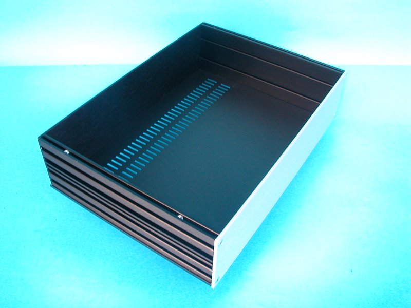
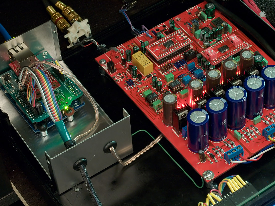
The Amplifier Stage
The amplifier stage is based on the Tripath TA2022 and is built upon a DIY kit I purchased from 41hz.com. Unfortunately, this site does not exist anymore. The hyperlink points to an Internet archive where you can see some of the pages of the site.
The amplifier stage was quite easy to assemble. It requires three different operating voltages to operate. The power supply unit shown on the right of the block diagram generates these supplies:
- 32.5V
- -32.5V
- 5V
The first two are produced by a couple of classical rectifier circuits which are based on a Graetz bridge and are followed by a couple of traditional transistor-based linear regulators I bought along with the amplifier stage. The input AC voltage is 25Vrms, provided by a dual secondary winding power transformer (T2). This part is an example of a component which was recycled from a previous project.
5V power rail is required to provide the bias voltage to the Tripath integrated circuit. It is generated by another linear regulator I bought from 41hz.com too.
The analog signal inputs are connected to RCA connectors mounted on the rear panel of the enclosure. This allows feeding easily the amplifier stage with virtually any analog source other than the USB DAC, as the connection is made outside the enclosure.
With regard to heat management, I thermally coupled the TA2022 to the aluminum enclosure which acts as a heat sink as well.
The DAC section
To implement the digital-to-analog converter, I purchased a ready-to-use board based on the Cirrus Logic CS4398, as I didn’t have the time to assemble one. Optionally, this board can be populated by a small plug-in card integrating the Cirrus Logic CS8421 sample rate converter. This card allows oversampling the input stream to 192 kS/s. I bought this option as well.

Unfortunately, it seems this product is not available anymore. When I bought it, it was easy to find instead.
When connected to a Linux PC, the DAC board is detected as follows:
[code]
[ 3.948579] usb 3-9.3: New USB device found, idVendor=08bb, idProduct=2902
[ 3.948580] usb 3-9.3: New USB device strings: Mfr=1, Product=2, SerialNumber=0
[ 3.948581] usb 3-9.3: Product: USB Audio CODEC
[ 3.948582] usb 3-9.3: Manufacturer: Burr-Brown from TI
[ 3.948651] usb 3-9.3: ep 0x85 – rounding interval to 64 microframes, ep desc says 80 microframes
[ 3.949494] input: Burr-Brown from TI USB Audio CODEC as /devices/pci0000:00/0000:00:14.0/usb3/3-9/3-9.3/3-9.3
:1.3/0003:08BB:2902.0004/input/input21
[ 3.976067] cgroup: new mount options do not match the existing superblock, will be ignored
[ 3.999836] hid-generic 0003:08BB:2902.0004: input,hidraw3: USB HID v1.00 Device [Burr-Brown from TI USB Audio
CODEC ] on usb-0000:00:14.0-9.3/input3
[/code]
The board came with a multiple winding transformer providing the following output voltages:
- 13Vrms (x2)
- 8Vrms
These voltages are input directly to the DAC board as it integrates the PSU stage generating the DC voltages required by the conversion circuit. The same board also provides other audio input interfaces in addition to the USB port:
- S/PDIF (coaxial cable)
- optical.
Adding the Bluetooth Receiver
Last year, I decided to add a new input source. Nowadays, smartphones have become inseparable companions. As such, I thought that adding a Bluetooth audio receiver was a good idea as it allows playing remotely your favorite playlists stored on your mobile phone.
I bought a cheap receiver on eBay like the one shown in the following picture.

This receiver is designed to be plugged into a USB port from which it only gets the power. In my case, I pierced one side of the enclosure to place a USB type A panel mount female connector:

I connected just the ground and the 5V pin in order to power the Bluetooth receiver. I didn’t add a new power supply for the receiver. Instead, I used one of the 5V supply units integrated into the DAC board. Specifically, I used the one used to power the digital domain of the board.
The connection of the receiver’s output to the amplifier stage was trivial: as the connection is outside the enclosure, I just used a 3,5mm jack/RCA cable.

Notes
Featured image source: https://fthmb.tqn.com/e2Lyg5m2mi0h-ooYS-WXpkTVUhw=/768×0/filters:no_upscale():max_bytes(150000):strip_icc()/GettyImages-174750928-58a48cc35f9b58819cc45552.jpg